 |
Learning How To Use Fusion 360
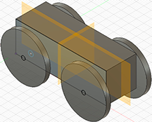
This will be the students first steps using Fusion 360, a mechanical engineering computer aided design application made by AutoDesk. Last year in ECS, these students made a basic car using Tinkercad, now they will make the same car but will use Fusion 360.
|
 |
|
|
Purpose |
|
| A. Open & Explain the Fusion 360 Interface |
Students will open Fusion 360 for the first time and learn about the interface. |
Click here. |
| B. Explain how to Organize & start a Project (& mm vs. inches) |
Students should start by drawing a Model of what they want to build. Then they should think about what is the main part of the project (Body), what are the stand alone parts that work in tandem with the main part (Components), and what are the additional features added to the Body and Components that help it function correctly (Features). Note: The Body and Components are all printed separately, even though they may eventually be assembled together. Also, usually you will begin by building the Body, but then you need to decide the order in which all the additional Components and Features should be created. |
Click here. |
| Launch Fusion:"New Design" |
!!Fusion changed how projects are built. The original method had the user add "Components" as they developed their project. In 2026, Fusion introduced a new method called "Intent Driven Design." Problem, Students/Engineers could no longer access commands to use "Components" when trying to change old projects or when they were developing new projects. Solution...When you set up a new project or even editing an older project, you can select "Hybrid" which allows you use "Components" with both your old and new tools. |
Click here. |
| C. Inches or m.m. |
Students will learn how switch the project from inches to m.m. |
Click here. |
| 1. Sketch Car Body |
Students will use the following tools to Sketch a Rectangle. A Sketch is a base 2D image of the Model they intend to create. They will also be introduced to the value of "Esc" & Edit/Undo.
- 1a.Rectangle Tool & Line Tool
- 1b. Sketching Constraint Tools
- Perpendicular
- Parallel
- Horizontal
- Dimension
|
1a. Rectangle & Line Tools
Click here.
1b. Constraint Tools
Click here. |
| 2. Make 3d Car Body |
Students will use the Extrude tool to create a 3d car body. |
Click here. |
3. Navigation: Viewing the Object
(Different Angles)
|
Student will Rotate, ZoomIn/Out, and Move the object. |
Click here. |
| 4. Create Hole thru Car Body |
Students will create a hole through the car body for the axle to spin using the "Center Diameter Circle" & Extrude tools. |
Click here. |
| 5a. Replicating and Placing Holes. |
Students will replicate the body hole and place at another matching spot on the car body using the Rectangular Pattern Tool. |
5a. Click here.
|
| 5b. Terminology |
An explanation of the some of the more common terms you will come across: Sketch, Body, Component and Face, |
5b. Click here. |
| Understanding...The Timeline! |
This is an explanation of the Timeline and how it can be of tremendous use to you!
Note: The Fast Car that you will be viewing was just made up in order to help you better understand how the Timeline works and is not part of the training sequence you have been following. Click here. |
|
| 6. Create the Axle and Body Hole... |
Students will be taught that there are two different ways to create the axle and body hole. Students will find both of these tools very useful.
- 6a. "Center Diameter Circle Tool"
- 6e. "Offset Tool".
|
|
"Center Diameter Circle Tool"
6a. Axle 1: Using "New Component" and "Center Diameter Circle" Tool. Click here.
6d. "Mirror Tool" (or replicating) the Axle Into 2nd Body Hole. Click here.
|
"Offset Tool."
6e. A 2nd Way... Creating the axle with the "Offset Tool." Click here.
6f. A 2nd Way... "Mirror Tool" (or replicating) the Axle & Hole. Click here. |
| 7. Create the Wheel & Hole |
Students will create the wheel using "New Component", "Center Diameter Circle Tool" and "Extrude" tools. |
Click here. |
| 8. Mirror Wheels Onto Axles |
Students will be taught how to use the "Multiply" tool to both create and place the wheels to the exact spots, instead of recreating the wheel three additional times, |
Click here. |
| 9. Exporting File To Instructor To Be Printed on a 3D Printer |
In the Browser Window (left side of Fusion interface), select the component you want printed (It should turn light blue). Then Right Click on the light blue component, and select in the Drop Down Menu "Save As / Mesh". Select the Format that you would like to save:
- Object "1 selection" - make sure your component is still blue.
- Format: "STL" (Binary).
- Click OK.
- Save As - title / type / and notice where you are saving the file.
- The Body becomes transparent and the Component becomes dark gray.
- Select the "Home" Button in the Top Left Tool Bar.
- Select "Projects" in the Left column. Note: I saved my file to the "Admin Project" - You need to know where you saved your file. I see my file in a list with other files in the main window. Select the file and then click on the 3 dots to the right of the file name and Select "Share" - copy the link and paste it into an email and send to the instructor.
- The instructor opens the email, clicks on the link and the student's .stl file will appear in their online Fusion Projects Folder. Look for the download icon in the Top Menu (right side) and download the .stl file to the instructor's computer. The instructor can now open the file and print in Makerbot.
The student will place the ".stl" files in a folder, upload to their Google Drive and share the folder with the instructor.
fusion.online.autodesk.com/login |
Click here. |
| |
The Following Section is Part II and is still in development. |
|
| 6. Create Wheel Well |
Students will develop the wheel wells for the car. |
Click here. |
| 7. Create Wheels |
Students will develop the wheels for the car using a Positive Extrude. |
Click here. |
| 8. Move Wheels into Wheel Well |
Angle view to see inside of wheel. Select it. Right Click/MoveCopy_Click on the inside of wheel again. Pull Arrow 3mm into ww. |
Click here. |
| 9. Mirror Wheel in Wheel Well |
MM / Construct / Midplane. Select both opposite exterior faces. MM / Create / Mirror. Select Object / Select the new mid plane (Gold) |
Click here. |
| |
|
|