Assembly
Always assemble the parts over the plastic container you were given. This will reduce your frustration from having to search for parts you drop on the ground.
Note: if you find that any of my instructions are inaccurate or not clear, please let me know so that I can improve it for you!
Nuts
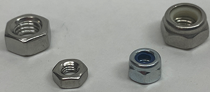
There are two nuts you will be using: Standard Nuts (we will refer to as a "Nut".) & Locking Nuts.
Look at the image. "Nuts" are on the left and "Locking Nuts" are on the right. Notice the plastic in the "Locking Nut." That little bit of plastic keeps the screw or bolt from unwinding out of the "Locking Nut," unlike the standard "Nut". The instructions below will explain when to use each nut and how to use them.
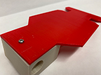

1. Attach the Motor Mount to the Base
- Line up the Base to the Motor Mount. Connect them with a screw (m3 #10/red), but no nut.
- Ask the teacher to drill a hole (1/8 bit) through the two existing holes in the Motor Mount through the Base. Connect the them with a screw (m3 #12/green) and a nut.


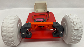
2. Assemble & Connect the Steering Column
- Place the Ball Bearing between the Steering Column.
- On the short Square Arm, set a screw (m3 #10/red), and locking nut.
- Using your Needle Nose Pliers, file down the plastic portions of the Steering Rack that will directly make contact with the Steering Column. This will allow your wheels to turn easily.
- On the Curved Arm set a screw (m3 #20/black), with washer and locking nut and attach to Steering Rack. Note: The Locking Nut has a little bit of plastic that allows the screw to stick to the nut. You want the arm to move loosely at the point it is connected to the Steering Rack...so do not over tighten! Tighten just enough so that the screw sticks in the Locking Nut. Also, the washer allows the Arm to move more smoothly...but if you have difficulty trying to connect it...then don't use it.
- Time to connect the Steering Column. Line up the two holes on the base of the Steering Column with the holes on the Base Plate (Take a look at the Models). Connect the Steering Column to the Base with a screw (m3 #14/orange), with washers and locking nut. Again, tighten just enough so that the screw sticks in the plastic of the Locking Nut - you want the Steering Coumn to turn easily. I use the washers to keep plastic from touching plastic - this allows the steering column to turn more smoothly - but it is your choice if you want to add.
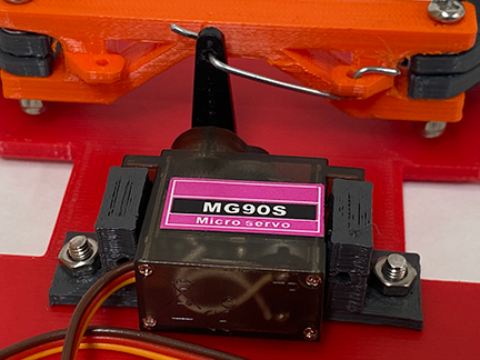
3. Assemble & Connect the Servo Motor
!I don't have replacement parts. Please attach the small parts over your plastic container. If they fall on the floor, it will be hard for you to find.
Call me over and I will help you attach the Servo Motor to the Steering Column and Base. These are the steps I will follow:
- Attach the Servo Motor to your Servo Mount with the supplied screws.
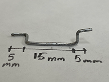
- I will create a Control Rod from a paper clip for you.
- I will detach the Servo Motor Arm from the Servo Motor.
- I will attach the Control Rod to the Steering Column.
- First, Connect Rod to Steering Rack (slide up through bottom).
- Second, Connect Rod to Servo Arm (slide up through back).
- Reattach the Servo Arm to the Servo Motor.
- Line ups Servo Motor on Base and attach (drill hole and connect with screws (m3 #10/red_ 1/8'' bit) and bolts).
4. Attach Front Wheels To Steering Column
- Insert nuts (M5 nut) into either end of the wheels (I have a hammer if you need to slightly tap it in.)
- Insert bolt (M5 40mm) through hole in steering column (inside to outside), through a Locking Nut on the exterior of the wheel. This will take some time, since you have to turn the bolt through the Locking Nut. I held the locking nut firmlhy with a pair of pliers and turned the bolt as quickly as I could with a Hex Key. (Note: Do not allow the pliers to touch the threads on the bolt!). Approach me and ask if I can use the drill to attach it for you...it will save you alot of time.
- Add a washer to the bolt, and finally connect the wheel by screwing the bolt through the nuts that you placed on both sides of the wheel. (If the wheel contacts the Base, call me over and I will trim the base.)
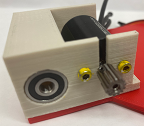
5. Attach the Motor & Ball Bearing
- I will provide you with a motor in which the Pinion Gear is already attached to the Motor Spindle.
- Look at the motor and notice that their are two screw holes across from each other that are bigger than the rest. Slide motor spindle through opening. Line up the holes with the holes on the Motor Mount. Insert a screw (m3 #8/yellow)through the motor mount hole and into the motor and attach.
- Line up the Ball Bearing with the hole on the Motor Mount and use your thumb to push it into the hole,

6. Assembling The Rear Axle, Wheels & Gears
6a. Attach Locking Nuts & Nuts to Rear Wheels.
- Attach 3 Nuts to the rear wheels...but the final Nut that you attach must be a Locking Nut.
- Note: The Locking Nut will appear on the exterior side of the back right wheel. This Locking Nut will keep the Bolt (or rear axle) from unscrewing.

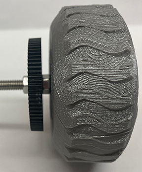
6b. Assemble Right Wheel, Axle (threaded bolt) and Nuts.
- Hold the Threaded Bolt with your Left hand and spin a nut approximately 3 inches onto the bolt from the right side.
- Slide a washer onto the bolt up to the nut.
- Spin the Spur Gear onto the bolt up to the washer (apply a little pressure as you spin it from right to left on the bolt).
- Slide on another washer up to the Spur Gear.
- Spin on a Nut up to the washer.
- Line up all the parts so that when you add the wheel, the bolt should just barely be sticking out the right side of the wheel with the Locking Nut. Once you feel it is lined up, begin screwing the wheel onto the bolt, from the right side, toward the Spur Gear. Remember, the Locking Nut must be on the right exterior side of that wheel. This will take some adjustment.

6c. Line Up The Gears
- Add at least one washer against the left side of the gear, then a bolt against this washer and then a final washer between the bolt and the Ball Bearing.
- Note: I use washers to fill space and reduce friction between moving parts. You will have to decide when and when not to fill gaps with washers and nuts.
- Slide the Axle through the Ball Bearings. The large Spur Gear will eventually make contact with the small Pinion Gear. Slightly wabble the gears so they slide onto each other. The large Spur Gear should sit on the outer portion of the small Pinion Gear. !Do not let the large Spur Gear make contact with the small black screw that is holding the small Pinion Gear onto the Motor Spindle!
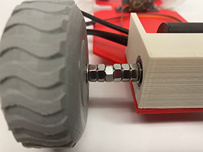

6d. Assemble Axle, Nuts And Wheel
- From where the Axle exits the Ball Bearing on the left side of the Motor Mount, add a washer, 6 nuts, another washer and finally screw the axle through the wheel.
- Note: the 6 nuts primarily fill space. If you need more axle on the right side to line up the gears better, then make adjustments and send it from all this excess on the left side.
- In order to keep the Left Wheel from spinning off the axle while driving, allow the bolt to stick out of the Left Wheel just enough to slide on a washer and screw on a locking nut (see image)!

![]()
7. Connect Battery & Transformer
First, take a look at the battery. You will notice that there are two cables extruding from it. One has a Red Cap and the other has a White Cap. Ignore the White Cap cable - do not touch it. Only work with the Red Cap cable.
Figure out where you would like the Battery and Transformer to be placed, mark the holes that will be drilled with a pencil. Call me over and I will drill your holes for you.
8. Connect Radio Control System
We are using the GooLRC - Radio Contol (2.4Ghz)
Have your teacher provide you with a matching controller and receiver. Your teacher in advance will sync the transmitter and receiver and mark them with a matching color.
Here are my NOTES for syncing the Transmitter and Receiver - students can ignore these notes.
Insert 4 AA batteries into the transmitter. Solid Green is Good! Flashing Green...replace the batteries.
Turn the transmitter's power off.
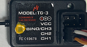
9. Connecting the RC Car to the Transmitter/Receiver:
- Turn everything off. Remove the Match Line and Power Line.
- Insert the Servo line in Ch 1 - Orange wire to the left.
- Insert the Power line in Ch 2 - White line to the left.
- Turn the Transmitter and RC Power button on and squeeze the throttle...it should work...I hope!
Note: If the wheels spin while off the ground, but your car does not move while on the ground...give it a little nudge with your toe...it should go!
![]()
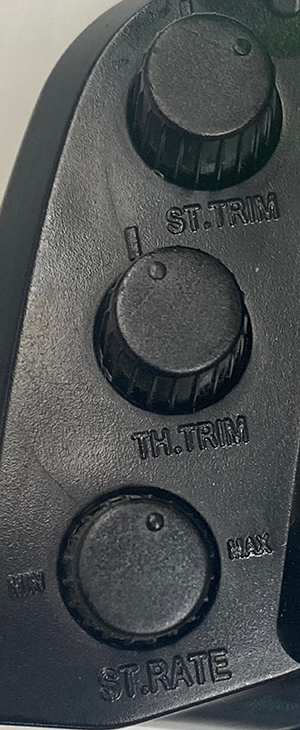
10. Modifying Your Car Performance Using The Transmitter
- Steering Trim (Ch 1/knob): Allows the user to adjust the steering wheel alignment. It will help you help your car to track in a straight line and not pull to one side. Hint: Drive your car on a flat surface at a low speed - now turn the "ST Trim" knob to make adjustments.
- Throttle Trim (Ch 2/knob): Allows the user to adjust the rear wheel. The Throttle Trim is not useful for Electric vehicles like ours, just gas powered cars, so keep the knob in the neutral position.
Note: If your car has steering but no Throttle power to drive, most likely the Throttle Trim knob has been turned. Slowly turn the knob while pressing the Throttle and the power to the rear wheels will return. - Steering Rate: Allows you to adjust the Servo Arm to travel to positions that are useful, not the full 120 degrees allowed. If you adjust it to far, it can restrict you from steering, Just keep it in neutral.
- 'ST' Switch (steering): "N" (neutral) - when you turn the Steering Wheel counter clockwise, the car will turn left. "R" (reverse) - when you turn the Steering Wheel clockwise, the car will turn right.
- "TH" Switch (throttle/power) - "N" (neutral) - when you press the Throttle, the car will drive straight. "R" (reverse) - when you press the Throttle, the car will drive backwards. If the wheels are moving in the wrong direction, just switch how the cables connect between the motor and the Power Transformer.
- "TH Limit" - Increases or decreases the speed: "L" = low, "M"= medium, "H"=high.
My Transmitter Settings Recommendations:
- "TH Limit" = "L"
- "ST" = "N"
- "TH" = "N"
- "ST TRIM": Adjust till wheels are straight.
- "TH TRIM": neutral
- "ST RATE": neutral