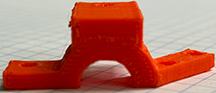
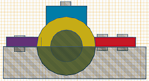
Ask to see the Model Upper & Lower Steering Column with the Ball Bearing. This will help you understand what you are building.
1. Build The Ball Bearing Structure
First, build the structure for the ball bearing. It is simple to do. Remember, you already built a structure for the ball bearing when you built the "Motor Mount."
You can either look at those measurements and copy them...or do what I did and copy the "Motor Mount Ball Bearing Hole" and paste it TWICE in a new file you will create and name it "Lower_Steering Column." Let one of the two holes remain a hole, and make the other one a solid color.
I am going to save you some time...
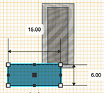
- The measurements of the hole are: 16.50mm x 16.50mm / Width: 6.0 mm.
- The measurement for the solid colored ball bearing structure that you will create is: 18.50mm x 18.50mm / Width: 9.50.
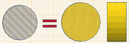
Center the Ball Bearing Hole inside inside the larger solid colored ball bearing structure that you just created (Turn it: Center it in both the "X" and "Y" axis.). Be precise! You just completed the most important part!
!Hint: In order to clearly see an object inside of another object...make both objects transparent!
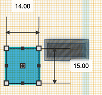
Add A Base Plate Connector To The Ball Bearing Structure
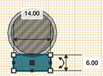
- Add a square: H14mm x L15mm x W6mm (see image below.)
- Attach to the Ball Bearing Connection - view the model and images - Need not be perfect, just eyeball it, but make sure the square does not puncture the inner ball bearing space when you connect.
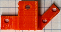
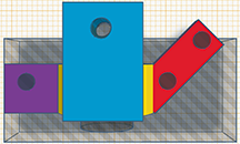
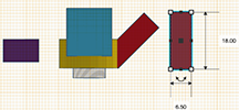
2. Build The Arms.
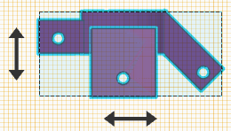
Look at the model and/or the images above. The arms do not need to be precise measurements. Notice how one arm is a square (purple) and its purpose is to allow a bolt to connect the Upper & Lower Steering Column together (simple!). The second arm is is at an angle and connects the Steering Column to the Steering Rack. If you look at the images below, you will see that I made it from one rectangle. So make it and rotate it. Now connect the square and the rectangle to the ballbearing structure. It is ok to punture the hole where the ball bearing will go because when you "Group" it, that piece will disappear.
Square Arm: H: 7, W: 3, L: 11
Rectangle Arm: H: 18, W: 3, L: 6.5
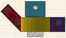
Add The 3 Holes: All Holes: 3.18mm x 3.18 mm.
Again, you don't need to be precise, but try to center it and keep it approximately 2mm from the end of each arm.
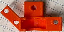
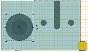
3. Build Axle Hole
Again, look at the model and/or images above. Create a hole (I created a 10mm circle) and send it directly through the center of the Ball Bearing Structure.
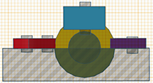
Finally...Delete The Top Of The Ball Bearing Structure.
Look at the 'Tinkercad Screen Shot' directly above. Create a 'Square' that is a 'Hole' and precisely line it up so that it deletes the top half of the 'Ball Bearing Structure' you created.
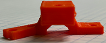
It is very important to line up the the flat 'cut off' part of the steering column and the base of the square and the base of the rectangle or else the steering column will not print correctly. Trick: Look at the image directly above. Use the transparent block you created above to cut off half of the ball bearing structure to also cut off the base of the rectangle and square...this will keep the base of all 3 level with each other.
Congratulations...You are done. Now go to print!
4. Create The Upper Steering Column
Duplicate this file (right click "Duplicate"). Save it as Upper Steering Column. Open this new file.
Group this Upper Steering Column so that it is now one structure.
Select it.
Click on the "Mirror" button in the top right menu.(see image below).
Select the arrow underneath the steering column and it will automatically flip it.