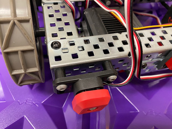
Create a program in which your robot drives forward and stops when the Bumper Switch touches an inanimate object (wall, box, etc.). It waits two seconds, backs up and then turns 90 degrees and moves until the bumper touches another object. Your robot continues to bump and turn until you turn it off.
Image of Bumper attached to robot: Click Here.
Video of robot with Bumper Sensor. Mobile or You Tube.
Helpful Hint: If you would like to save time by Copy/Paste code from one program you write to another...just click on the segment of the code you would like to copy, then select "Control" "C" - open the new program and "Control" "V". It will appear!
Create a New program.
Remember to add a "Bumper" in the Device Menu.
The program you write is a simple If/Then Statement in a Forever Loop:
- When Started
- Forever
- If Bumper / Then Coast _ Stop Driving
- Reverse _ 2 seconds _ Stop.
- Turn 90 degrees.

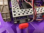
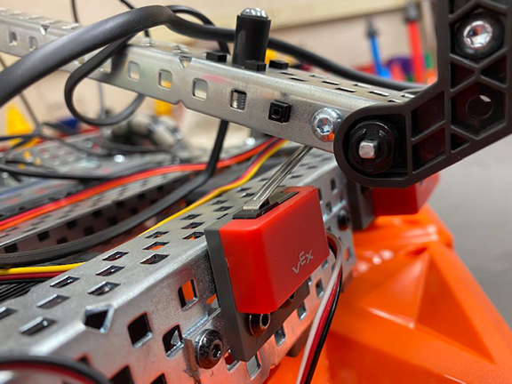
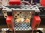
Create a program in which a Limit Switch stops the arm from over lowering and hitting the steel frame.
Image of Limit Switch attached to robot: Click Here
Look at the image I provided to see how you should attach the Limit Switch - be careful, you don't want the arm to damage the metal tab on the switch.
- This program will require you to use your controller. Instead of writing a new program, open your "Mine Field Challenge" program & Save As "Limit Switch."
- Remember to "Add A Device" - Limit Switch- in the Device Menu.
- Change Arm Lowering Velocity to 20%.
- Two options when programming the Limit Switch to stop the descending arm:
- Note:
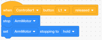
- Here is a program that will stop your arm from slowly descending after you raised and stopped it. Click here. Apply it to L1, L2, R1, R2.
- I will test your program by pressing the Limit Switch with my finger as it rises and descends.
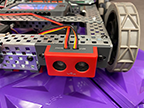
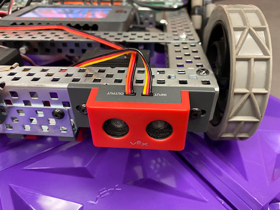
Program the Ultrasonic Range Finder so that the sensor will stop the robot 10 inches from an object. Your robot shall wait, back up and then turn (90 degrees) and moves in that direction until it senses another object. Your robot continues to 'sense' and turn until you turn it off.
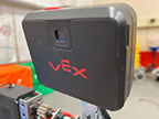
Image of Ultrasonic Range Finder attached to robot:
Click Here.
Video of robot with Ultrasonic Range Finder:
Mobile or You Tube.
Open your "Bumper" Program. "Save As" 'Ultrasonic'. Go to the "Devices Menu" and set up a New Device: 3 Wire - Ultrasonic Range Finder.
You only need to make one change to this code: RangeFinder_Distance In_ Inches < 10.
Note: I accidentally chose "<" instead of ">" and I could not get the robot to stop and turn until it saw an object MORE than 10 inches.
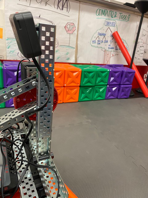
Position your robot in the center of the Competition Court. The boxes Purple, Green, Orange and Yellow cones will be positioned on the four sides. Program the Robot so that it will drive forward and when it senses one of the four colors, the robot will back up to the center of the course, turn 90 degrees and begin to move toward the next color. The robot needs to sense all four colors and return to center. Model Vision Sensor / (You Tube)
Image of how I attached my Vision Sensor to my robot - You may attach it any way that works for you.
Click Here.
The following video is very helpful in showing you how to get your Vision Sensor to recognize different colors. Click Here.
- Connect the Vision Sensor.
- My Hints For You: 1. Training The Vision Sensor, & 2. Programming The Vision Sensor.
- Program the Robot/Sensor.
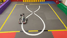
Program the Robot so that it will follow the White Elliptical Line and the Squigley Line in class. Model Line Sensor / (You Tube)
Image of Line Sensor attached to robot:
Click Here.
You need to make a choice as to how you attach your Line Sensors to your robot:
- Move forward as long as the sensor is over the dark carpet, and 'IF' the line sensor touches the White tape, 'Then' it will turn back to dark. (I recommend you choose this option).
- Or, you can engineer your robot to move forward as long as the sensor is over White tape, and 'IF' it touches the dark carpet, 'Then' it will shift back over the White tape.
I recommend you view the instructors robot to see how the Line Sensors were attached.
- Add the 2 Line Tracking/Color Sensors to the bottom of your robot. I recommend you borrow a roll of White Duct Tape from me. Hold it between the two sensors on the bottom of your robot...this is how far apart the sensors should be from each other (if you chose option 1 when you attached the Line Sensor to your robot)!
- Create a New Program and title it LineSensor.
- Remember to go to the "Devices Menu" and set up a New Device: 3 Wire - Line Tracking / Color.
- You have two programming choices:
- Drivetrain: In the Device Menu add a Drivetrain and program the sensors to turn Left or Right when they sense a specific Reflectivity.
- Motors: In the Device Menu add 2 Motors (With 2 motors, the wheels will work independently from each other.). Program the sensors to turn Left or Right when they sense a specific Reflectivity.
- Note: Both options work. I chose "Motors" because it gave me more flexiblity. Although, you will have to reprogram using "Drivetrain" when you attempt the next project..."The Sensor Puzzle."
Line Sensor Hints: Tips on how to successfully program your robot with the Line Sensor. Click Here!
"The Sensor Puzzle?"
Good Luck!
Hint: Copy & paste your successful programs into one program. Make sure all the programs that in effect turn the wheels are either based on Motors or Drivetrain...but not both. Now test each program individually - when they work correctly, merge them into one program. Note: You will need to reestablish the colors for the vision sensor.